What Are Geared Motors and How Do They Work?

Time:2026-09-30 Author:Sienna
0%

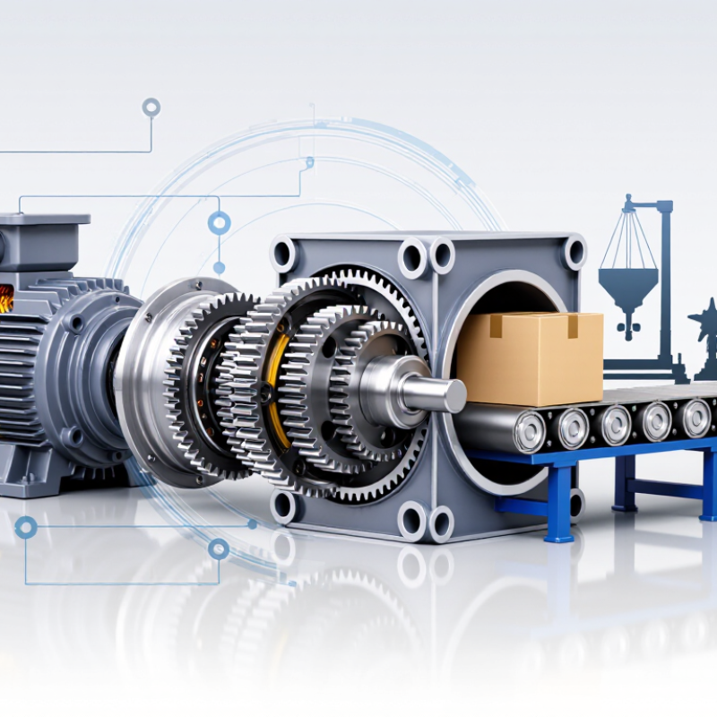
What Are Geared Motors and How Do They Work? This question matters wherever controlled motion meets continuous production. Geared Motors combine an electric motor with a gearbox. The motor produces rotation, while the gearbox changes speed and torque. Inside the housing, gears mesh through carefully selected ratios. A conveyor may run slowly, yet move a heavy carton without stalling. That practical balance explains why geared motors appear in packaging lines, elevators, mixers, robotics, and automated warehouse systems.

The U.S. Department of Energy reports that motor systems consume more than half of the electricity used in American manufacturing (U.S. DOE, Motor Systems). This figure shows why motor selection deserves engineering attention, not guesswork. A gearbox can reduce speed and increase output torque, but it also introduces friction, heat, noise, and maintenance requirements. Small details matter. Poor alignment can damage bearings. Incorrect lubrication can raise operating temperature. The International Energy Agency also identifies electric motor systems as a major global energy-efficiency opportunity (IEA, Energy Efficiency 2023).

A smaller motor is not automatically more efficient. Nor is a larger gearbox always safer. Engineers must compare load, duty cycle, starting torque, ambient temperature, service factor, and expected operating hours. The explanation is not perfectly simple. Real installations often behave differently from catalog calculations. Dust, shock loads, and poor ventilation can change performance quickly. This guide examines how Geared Motors transfer power, how their components work together, and how users can evaluate efficiency, reliability, and application fit with greater confidence.
What Are Geared Motors and How Do They Work?

What Is a Geared Motor?

What Is a Geared Motor?

A geared motor combines an electric motor with a gearbox in one compact drive unit. The motor creates rotational force, while the gearbox adjusts speed and torque. Small gears turn quickly. Larger output gears rotate more slowly, but deliver stronger turning force.

This arrangement suits conveyors, mixers, automated gates, packaging equipment, and mobile machinery. In practical installations, the gearbox often determines whether a motor performs smoothly or struggles under load. Engineers select gear ratios according to speed, torque, duty cycle, and available space.

A 20:1 ratio, for example, can reduce output speed substantially while increasing usable torque. Actual output also depends on efficiency, lubrication, alignment, and heat.

The details matter.

Industry data supports the growing role of these systems. Grand View Research estimated the global gear motor market at more than 20 billion dollars in 2023, with continued growth expected through the decade.

The International Energy Agency also reports that electric motor systems consume roughly half of global electricity. Even modest efficiency improvements can therefore produce meaningful energy savings.

In operation, electricity energizes the motor’s windings and creates a rotating magnetic field. That field turns the rotor and input shaft. The gearbox then transfers motion through meshing gears.

Friction, backlash, and bearing losses reduce the final output slightly. This is where simplified explanations become imperfect. A geared motor does not automatically provide maximum efficiency. Proper sizing and maintenance still decide its real-world performance.

Core Components and Their Functions

What Are Geared Motors and How Do They Work?

Core Components and Their Functions

A geared motor combines an electric motor with a gearbox. The motor creates rotation, while the gearbox reduces speed and increases usable torque. This arrangement lets a conveyor move steadily, even under changing loads.

The motor usually contains a stator, rotor, windings, and a cooling structure. The stator produces a magnetic field. The rotor turns inside it. A gearbox then transfers this motion through gears, shafts, bearings, seals, and lubricant. Each component has a practical duty. Gears control speed and torque. Shafts carry mechanical force. Bearings reduce friction. Seals keep lubricant inside and dust outside. The housing protects the assembly and supports alignment.

Small details matter.

Poor alignment can create vibration, heat, and early bearing failure. In field inspections, technicians often check unusual noise before measuring temperature. That approach is useful, but incomplete. A quiet gearbox may still have contaminated lubricant or excessive backlash.

The International Energy Agency reports that electric motor systems consume roughly half of global electricity. This figure explains why efficient drivetrain design deserves close attention. A properly selected gear ratio can reduce unnecessary motor strain. However, efficiency depends on load patterns, lubrication, operating temperature, and maintenance quality. A motor running far below its intended load may waste energy through avoidable losses. Sensors can monitor speed, current, and temperature, but they cannot correct poor installation. The component is intelligent only when the system around it is properly managed.

How a Geared Motor Transmits Motion

A geared motor combines an electric motor with a gearbox to control motion. The motor creates rotational force, while the gears adjust speed and torque. A 10:1 gearbox, for example, can reduce a 1,800-rpm motor to roughly 180 rpm. The trade-off is stronger turning force at the output shaft.

Gear teeth transmit motion through controlled contact. The input gear drives another gear, and each ratio changes rotational speed. Output torque is approximately input torque multiplied by the reduction ratio and gearbox efficiency. If a motor supplies 1 newton-meter, a 10:1 gearbox operating at 85% efficiency may deliver about 8.5 newton-meters. Friction creates the difference. Heat is visible near the housing.

This matters beyond mechanical design. The U.S. Department of Energy reports that motor systems can account for more than 70% of industrial electricity use. The International Energy Agency has estimated that electric motor systems consume about 46% of global electricity. Better speed matching can reduce wasted energy, especially in conveyors, pumps, and lifting equipment. In practice, I check the load cycle, starting torque, shaft alignment, and lubrication before selecting a ratio. The calculation is simple. The application is not. A gearbox that works smoothly at steady speed may struggle during frequent stops, shocks, or reversed motion. Gear efficiency also changes with load, temperature, and maintenance condition.

What Are Geared Motors and How Do They Work? - How a Geared Motor Transmits Motion

Category Data Dimension Technical Description Typical Value or Relationship
Definition Geared motor An integrated drive unit that combines an electric motor with a gearbox. The motor produces rotational motion, while the gearbox changes speed and torque. Motor + gear-reduction mechanism + output shaft
Motion Path Energy transmission sequence Electrical energy is converted into motor rotation, transferred through gears, and delivered as controlled rotary motion at the output shaft. Electric power → motor shaft → gears → output shaft
Motor Section Input speed The rotational speed generated by the motor before gear reduction. Speed depends on motor design, supply frequency, pole count, and operating conditions. Common industrial motor speeds include approximately 900, 1,500, or 3,000 rpm at 50 Hz
Gearbox Section Gear ratio The ratio between the input speed and the output speed. A higher reduction ratio produces a lower output speed and generally increases available output torque. Gear ratio = Input speed ÷ Output speed
Output Motion Output speed The speed delivered by the gearbox output shaft after the input speed has been reduced by the selected gear ratio. 1,500 rpm input ÷ 30:1 ratio = approximately 50 rpm output
Torque Output torque Gear reduction increases torque by trading rotational speed for turning force. Actual torque is reduced by mechanical losses in the motor and gearbox. Output torque ≈ Motor torque × Gear ratio × Efficiency
Power Mechanical power relationship Power remains approximately conserved apart from electrical and mechanical losses. When speed decreases, torque increases in proportion to the reduction ratio and efficiency. Power = Torque × Angular speed
Gear Types Spur gears Gears with straight teeth parallel to the shaft axis. They are relatively simple and efficient but may produce more noise at higher speeds. Suitable for straightforward, moderate-speed reduction systems
Gear Types Helical gears Gears with angled teeth that engage gradually. They generally operate more smoothly and quietly than spur gears but create axial thrust. Used where smooth transmission and higher load capacity are required
Gear Types Worm gears A worm screw meshes with a worm wheel to provide high reduction in a compact arrangement. Efficiency and backdrivability depend strongly on geometry, lubrication, and ratio. Common for compact right-angle drives and high reduction ratios
Gear Types Planetary gears Multiple planet gears rotate around a central sun gear. The load is distributed among several gears, allowing high torque density and compact construction. Used where compact size, high torque, and low backlash are important
Gear Types Bevel gears Conical gears that transmit motion between intersecting shafts, commonly changing the direction of rotation by approximately 90 degrees. Used in right-angle geared motor arrangements
Efficiency Transmission efficiency The percentage of mechanical input power delivered at the gearbox output. Efficiency varies with gear type, ratio, lubrication, load, speed, and manufacturing quality. Single-stage spur or helical systems may exceed 90%; multi-stage and worm systems are often lower
Control Speed control Output speed can be adjusted by selecting a different gear ratio or by controlling motor speed with an appropriate electrical drive. Fixed gearbox ratio + variable-frequency drive or electronic speed controller
Control Direction control The output direction depends on motor rotation and the number and arrangement of gear stages. Electrical control can reverse the motor where the motor and gearbox allow it. Reversing motor polarity or phase sequence, subject to motor type and controller design
Mechanical Design Backlash The small amount of angular clearance between mating gear teeth. Backlash allows lubrication and thermal expansion but can reduce positioning precision. Low-backlash designs are preferred for positioning and indexing applications
Mechanical Design Lubrication Gear teeth and bearings require suitable lubrication to reduce friction, wear, and heat. Lubricant type and level must match the gearbox design and operating conditions. Grease or oil lubrication, depending on gearbox size, orientation, speed, and load
Load Capacity Rated torque The continuous torque that the geared motor can deliver under specified conditions without exceeding thermal or mechanical limits. Must be greater than the application’s continuous load torque with an appropriate service factor
Load Capacity Starting torque The torque available when the motor begins rotating. It is important for overcoming static friction, inertia, and initial load resistance. Applications with high starting resistance require adequate motor starting torque and gearbox capacity
Applications Typical uses Geared motors are used wherever controlled speed, increased torque, compact power transmission, or repeatable rotary motion is required. Conveyors, mixers, feeders, actuators, automated gates, packaging equipment, and lifting mechanisms

Note: Actual speed, torque, efficiency, service life, and temperature rise depend on the motor, gearbox construction, load profile, duty cycle, lubrication, mounting position, and operating environment.

Common Types of Geared Motors

A geared motor combines an electric motor with a gearbox. The motor creates rotation, while the gears reduce speed and increase torque. This trade-off allows machines to move heavy loads with controlled motion. In equipment design, the gear arrangement often matters more than the motor’s appearance.

Spur geared motors use straight teeth and offer a simple, economical design. They work well in light-duty conveyors and basic automation systems. However, tooth contact can produce noticeable noise. Helical geared motors use angled teeth for smoother engagement and quieter operation. They suit conveyors, mixers, and systems requiring steady movement. They also create axial force. That detail matters.

Bevel geared motors change the direction of rotation, often by 90 degrees. They fit compact layouts where the motor and driven shaft must meet at an angle. Worm geared motors provide right-angle transmission and strong holding ability. Their sliding contact creates heat, so lubrication and cooling deserve careful attention. Planetary geared motors distribute load across several gears. This supports high torque, compact dimensions, and good efficiency, but the design can cost more. Not every application needs them.

Selecting a type requires more than comparing speed ratios. Check load, duty cycle, starting torque, mounting position, and operating temperature. A catalog rating is not a guarantee. Real conditions include vibration, dust, imperfect alignment, and frequent starts. An undersized motor may overheat, while an oversized unit may waste energy. The best choice is often a compromise, not the most powerful option.

What Are Geared Motors and How Do They Work?

Geared motors combine an electric motor with a gearbox to reduce speed and increase torque. The chart compares representative efficiency values for common geared motor types. Actual performance varies with gear ratio, load, lubrication, and operating conditions.

Key point: Planetary and helical geared motors typically provide high efficiency, while worm geared motors offer compact, high-ratio reduction with comparatively greater power loss.

Applications and Selection Considerations

What Are Geared Motors and How Do They Work?

A geared motor combines an electric motor with a gearbox in one compact drive unit. The motor creates rotational power, while the gearbox changes speed and torque. Smaller gears can increase output force for lifting, moving, or positioning equipment. This exchange also reduces output speed and may create mechanical losses.

Geared motors serve many practical applications. Conveyor systems use them to move cartons at controlled speeds. Automatic doors depend on steady torque during repeated opening cycles. In robotics, compact gear units help joints move with greater precision. Agricultural machines may use sealed designs where dust, moisture, and vibration are common. From hands-on equipment checks, I have found that noise often reveals alignment or lubrication problems before failure occurs. Small details matter.

Selection should begin with the required output speed, torque, and load pattern. A motor running continuously needs different thermal capacity from one used intermittently. Check starting torque, because heavy loads can exceed normal running requirements. Mounting position, shaft direction, and available space also affect compatibility. In wet or dusty areas, confirm the enclosure rating and sealing method. Low backlash matters for accurate positioning, but it can raise cost and reduce flexibility. Efficiency deserves attention, especially in equipment that operates for many hours. A neat specification can mislead. Real loads may surge, stall, or change direction unexpectedly. Measure the operating conditions carefully, then allow a practical safety margin.

FAQS

What is a geared motor?

A geared motor combines an electric motor with a gearbox. The motor creates rotation. The gearbox lowers speed and increases usable torque.

How does a gearbox change motor performance?

Gears transfer motion through shafts, bearings, seals, and lubricant. They trade output speed for greater mechanical force. Some energy becomes heat.

What are the main parts inside a geared motor?

Common parts include the stator, rotor, windings, gears, shafts, bearings, seals, housing, and cooling structure. Each part supports movement, protection, or heat control.

Why are alignment and lubrication important?

Poor alignment can cause vibration, heat, and early bearing failure. Contaminated lubricant can damage gears quietly. Noise checks help, but they are incomplete.

What are common geared motor types?

Spur units offer simple construction and lower cost, but they can be noisy. Helical units run more smoothly and quietly. Bevel units change rotation direction, often by 90 degrees. Worm units provide right-angle drive and strong holding ability. Planetary units support high torque in compact spaces.

How should I select a geared motor for a conveyor?

Check output speed, torque, load changes, starting torque, duty cycle, mounting position, and shaft direction. Consider dust, vibration, and available space. A catalog rating is not a guarantee.

What happens when a geared motor is undersized or oversized?

An undersized motor may overheat during starts or heavy loads. An oversized motor may waste energy and cost more. The strongest option is not always the best option.

Can sensors solve geared motor problems?

Sensors can track speed, current, and temperature. They cannot correct poor installation, wrong alignment, or unsuitable gearing. The system still needs practical inspection.

Where are geared motors commonly used?

They drive conveyors, automatic doors, robotic joints, agricultural equipment, mixers, and positioning systems. Sealed designs help in dusty or damp areas. Conditions vary widely.

Why does efficiency deserve attention?

Electric motor systems use a large share of global electricity. Correct gearing can reduce unnecessary motor strain. Efficiency still depends on load patterns, temperature, lubrication, and maintenance. Small losses add up.

Conclusion

Geared Motors are integrated drive systems that combine an electric motor with a gearbox to deliver controlled mechanical motion. The motor produces rotational power, while the gear train adjusts speed, torque, and direction to match the needs of a machine. Key components typically include the motor, gears, shafts, bearings, housing, lubrication system, and output connection. Each part contributes to efficient power transmission, smooth operation, and reliable load handling.

As the motor turns, its input shaft drives a sequence of gears. The gear ratio determines whether the output rotates more slowly with greater torque or faster with reduced torque. Common types include spur, helical, bevel, worm, and planetary geared motors, each suited to different space, load, noise, and efficiency requirements. They are widely used in conveyors, automation equipment, lifting systems, packaging machinery, and other industrial applications. Selecting the right model requires evaluating power, torque, speed, duty cycle, mounting position, operating environment, and maintenance needs.

Sienna

Sienna

Sienna is a skilled marketing professional with a deep expertise in our company’s core products and services. With a passion for innovation and detail, she plays a pivotal role in crafting insightful blog posts that not only highlight the unique features of our offerings but also provide valuable......