Choosing the Right Torque Sensors for Your Application? Start With the Measurement
Selecting Torque Sensors is not simply a matter of choosing the largest capacity. The sensor must match torque range, rotational speed, accuracy, environment, and installation space. A motor test bench may need a high-speed rotary sensor with low inertia. A tightening tool may require compact construction, fast response, and reliable overload protection. Small details matter.
According to Dr. Thomas Kleckers, a torque-measurement specialist at HBK, “The best torque sensor is the one that fits the measurement task, not merely the one with the highest specification.” This principle deserves attention. A sensor rated for 1,000 Nm may seem safer than one rated for 100 Nm. However, excessive capacity can reduce measurement resolution at lower loads. That mistake is common.
Define the real operating range first. Include startup peaks, reversing loads, vibration, and unexpected shocks. Then examine signal output, calibration requirements, shaft alignment, and data-acquisition compatibility. Environmental conditions also influence performance. Heat, dust, moisture, and electromagnetic interference can distort results or shorten service life.
The installation often reveals hidden problems. A rigid coupling may create misalignment. A poorly supported cable may introduce noise. We should admit that product datasheets rarely show the entire application story. Practical testing remains essential.
The following guide compares key Torque Sensors specifications and explains how to balance precision, durability, cost, and future expansion. The right choice should produce trustworthy data, not impressive numbers alone.
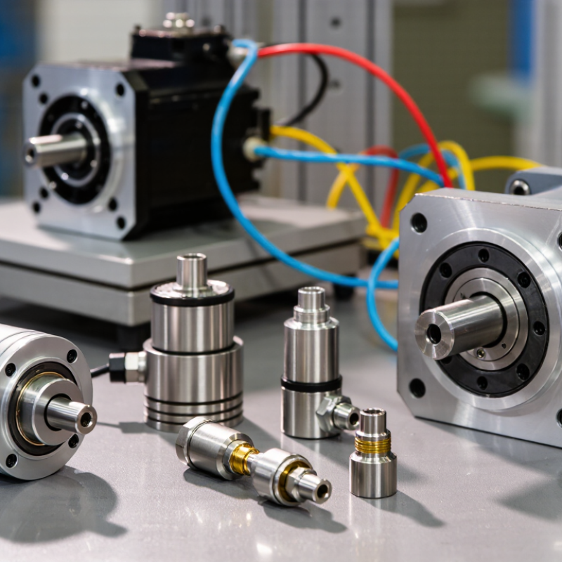
Torque is not simply rotational force. It is force multiplied by the perpendicular distance from the shaft axis. This basic relationship guides sensor selection. Static torque suits tightening verification, while dynamic torque requires stable readings during rotation. A sensor rated just above the expected load may improve resolution, but overloads can damage it quickly. Leave practical headroom.
Signal quality also depends on speed, temperature, vibration, and installation alignment. In factory testing, a small angular misalignment can create unwanted bending loads. That error may appear as torque. Check the sensor’s measurement range, overload capacity, output type, sampling rate, and calibration traceability. ISO/IEC 17025 principles support reliable calibration practices, although compliance alone does not guarantee a suitable measurement.
541,302 Demand for dependable torque data is growing with automation. The International Federation of Robotics reported 541,302 industrial robots installed worldwide in 2023, a 10% annual increase. More automated joints require compact, responsive sensing. The U.S. Department of Energy has estimated that motor-driven systems consume about 70% of industrial electricity. Accurate torque measurement can reveal friction, poor alignment, and wasted power.
The difficult part is often defining the real operating condition. Laboratory assumptions can be too clean. Review peak loads, startup shocks, duty cycles, and maintenance access with the people using the equipment. A perfect specification sheet can still mislead. Calibration intervals should also reflect risk, not habit.
Begin with the torque your machine actually produces, not only its rated motor power. Record continuous torque, peak torque, rotation speed, and expected overloads. A sensor should measure normal loads comfortably while surviving occasional spikes. Leave practical headroom. Too much capacity can reduce measurement resolution.
Operating conditions matter just as much. Check ambient temperature, humidity, dust, vibration, and possible exposure to cleaning fluids. Measure available installation space and inspect shaft alignment carefully. Misalignment can introduce unwanted forces and distort readings. In rotating equipment, confirm whether the sensor measures static torque, dynamic torque, or both. The difference affects the required design and signal processing.
Define the measurement objective before comparing specifications. Testing a gearbox may require high sampling speed and accurate peak detection. Process monitoring may need stable readings over long periods. Select suitable output signals, resolution, calibration method, and data-acquisition compatibility. Keep a written requirement sheet. It prevents vague assumptions from driving the purchase.
Perfect information is uncommon. If load cycles or temperature changes remain uncertain, document those gaps and test them. A controlled trial under realistic conditions can reveal problems that a catalogue cannot. I would also verify calibration traceability, installation instructions, and service support before approval. A sensor can be technically accurate yet unsuitable for daily maintenance routines. Practical reliability matters.
Choosing the right torque sensor starts with comparing how each technology behaves under real operating conditions. Strain-gauge sensors provide strong accuracy and useful static torque measurement. They suit test benches, assembly tools, and controlled production systems. Magnetoelastic sensors measure through magnetic changes and often tolerate vibration well. Optical sensors can deliver excellent resolution, but dust and shaft alignment may affect performance.
Performance depends on more than rated torque. Check accuracy, repeatability, overload capacity, bandwidth, and temperature drift. A sensor rated for 100 Nm should not constantly operate near its limit. Leave practical headroom. Dynamic applications require high sampling speed and low signal noise. Static systems may prioritize stability and long-term calibration. Contact-based designs can be simple and economical, while non-contact designs reduce wear and support continuous rotation.
Installation details can change the result. Shaft stiffness, coupling alignment, bearing friction, and cable routing may introduce errors that appear to be sensor faults. Environmental sealing matters in humid or dusty work areas. Verify the output interface and calibration method before purchase. A small mismatch can delay integration. Perfect measurement is uncommon. I would also question laboratory specifications when the sensor will face shock, heat, and frequent start-stop cycles. Testing under actual load conditions remains more reliable than choosing from a data sheet alone.
How to Choose the Right Torque Sensors for Your Application?
Matching a torque sensor to your measurement system requires more than checking its maximum range. Start with the expected working torque, speed, shaft size, and direction of rotation. Select a range that captures normal loads without leaving too much unused capacity. A sensor with excessive capacity may reduce useful resolution. Accuracy, repeatability, and hysteresis also matter when results support testing or process decisions.
Your measurement system must accept the sensor’s output type and electrical requirements. Check voltage, current, bridge signals, excitation, sampling rate, and bandwidth before ordering. Dynamic applications need a sensor and data system that respond quickly to changing torque. Consider mounting space, coupling alignment, vibration, temperature, and moisture. I have seen good sensors produce weak data because the installation was overlooked. The specification sheet helps, but it cannot reveal every workshop condition.
Tips: Record the real load profile, not just the rated motor torque. Confirm overload protection and calibration procedures. Test the signal chain with a known reference before full operation. Leave room for future loads, but avoid excessive range. Small details matter. Recheck cable routing and grounding. A rushed selection can appear acceptable during slow tests, then fail during rapid acceleration. That possibility deserves honest review.
| Application Profile | Typical Torque Range | Recommended Measurement Principle | Accuracy Requirement | Typical Speed Range | Suitable Output | Key Selection Priorities |
|---|---|---|---|---|---|---|
| Handheld Tool Testing | 0.1–50 N·m | Strain-gauge reaction or rotary torque sensor | ≤ ±0.5% of full scale | Typically below 3,000 rpm | Analog voltage, USB, or digital serial | Low-range resolution, overload protection, compact installation, easy calibration |
| Electric Motor and Drive Testing | 1–1,000 N·m | Rotary strain-gauge torque sensor | ≤ ±0.2% to ±0.5% of full scale | 1,000–20,000 rpm, depending on design | Frequency, voltage, CAN, or Ethernet | Rated speed, dynamic response, rotational balance, electrical noise immunity |
| Automotive Powertrain Testing | 10–10,000 N·m | High-speed rotary strain-gauge or magnetoelastic sensor | ≤ ±0.25% of full scale | Up to approximately 30,000 rpm for specialized designs | CAN, frequency, analog, or Ethernet | High-speed capability, torsional vibration bandwidth, temperature stability, overspeed rating |
| Industrial Gearbox Monitoring | 100–100,000 N·m | Flange-mounted or inline rotary torque sensor | ≤ ±0.5% to ±1.0% of full scale | Generally below 5,000 rpm | 4–20 mA, voltage, frequency, or fieldbus | High overload capacity, robust housing, shaft alignment tolerance, IP protection |
| Robotics and Servo Systems | 0.01–200 N·m | Compact strain-gauge or multi-axis force–torque sensor | ≤ ±0.5% of full scale | Application-dependent; often below 6,000 rpm | EtherCAT, CAN, USB, or analog voltage | Low inertia, fast response, small envelope, low hysteresis, simple controller integration |
| Pump and Fan Performance Testing | 5–5,000 N·m | Rotary torque sensor with speed measurement | ≤ ±0.5% of full scale | 500–10,000 rpm | Analog, frequency, or digital data acquisition | Continuous-duty rating, moisture resistance, speed synchronization, stable zero output |
| Static Bolt and Fastener Testing | 1–10,000 N·m | Reaction torque transducer | ≤ ±0.25% to ±0.5% of full scale | Not applicable or very low rotational speed | Millivolt per volt, analog voltage, or USB | High repeatability, minimal drift, overload resistance, suitable mounting geometry |
| Process and Material Handling | 50–50,000 N·m | Inline rotary or reaction torque sensor | ≤ ±1.0% of full scale | Below 3,000 rpm in many installations | 4–20 mA, voltage, or industrial fieldbus | Long-term stability, ingress protection, simple maintenance, compatibility with control systems |
Choosing a torque sensor starts with the installation, not the catalog. Define nominal torque, peak loads, shaft speed, direction, and available space. A sensor rated too close to the working limit may drift or fail during a short overload. I once saw a test setup produce unstable readings because the coupling was slightly misaligned. The sensor was accurate; the installation was not. Leave room for thermal expansion and tool access. Check whether the housing can withstand vibration, dust, moisture, and repeated shock. Keep cables away from motors and high-current wiring. Small details matter.
Calibration should be planned before the sensor is mounted. Record the measurement range, resolution, expected uncertainty, and reference standard. Use a traceable torque source, documenting applied points in both directions when reversal is possible. Allow the sensor to reach operating temperature before checking zero. Then compare readings at several loads, not only at full scale. A simple calibration sheet can reveal drift between shifts. Do not hide an inconvenient result. Investigate it. Check mounting bolts, friction, alignment, and signal conditioning before replacing the sensor. Calibration intervals should reflect duty cycle, contamination, and the cost of an incorrect decision.
Long-term reliability comes from repeatable habits. Inspect couplings, fasteners, seals, connectors, and cable strain relief during scheduled stops. Watch for a rising zero offset or unusual noise. These are early warnings. Keep installation photos and maintenance records with the sensor’s identification details. It sounds tedious, but memory is a poor maintenance system. Review the interval after the first few months. It may be too long or unnecessarily cautious. That adjustment is part of engineering, not a failure.
Planning guide for sensor capacity, installation, calibration, and long-term maintenance
The chart compares typical application peak torque with a recommended sensor rating. The planning examples use a 2:1 capacity margin to reduce the risk of overload caused by startup torque, impact loads, or transient spikes. Confirm the final rating with measured operating data and the sensor manufacturer's specifications.
During installation, keep the sensor aligned with the shaft, avoid bending loads, and use the specified coupling and mounting torque. Perform a traceable calibration before commissioning and at regular intervals, commonly every 12 months or according to the application's accuracy requirements. For maintenance, inspect couplings, cables, connectors, and zero stability at scheduled intervals.
Record continuous torque, peak torque, rotation speed, direction, and expected overloads. Use real machine loads, not only motor ratings. Leave practical headroom. Excessive capacity can reduce resolution.
Check temperature, humidity, dust, vibration, moisture, and cleaning-fluid exposure. Measure installation space carefully. Consider thermal expansion and tool access. Workshop conditions are often messier than specifications suggest.
Decide whether the sensor measures stationary torque, rotating torque, or both. Dynamic applications need suitable sampling speed and bandwidth. Rapid acceleration can expose weak signal response. Test it.
Confirm output type, excitation, voltage, current, bridge signals, sampling rate, and bandwidth. Check data-acquisition compatibility before ordering. A correct sensor can still produce unusable data through an unsuitable signal chain.
Misalignment creates unwanted forces and distorted readings. Inspect couplings, fasteners, shaft position, and available clearance. Slight misalignment once caused unstable readings in a test setup. The sensor was accurate; installation was not.
Select a range that captures normal loads while surviving occasional spikes. Avoid choosing capacity far above expected torque. Too much unused range may weaken useful resolution. Future loads deserve consideration, but guessing is not enough.
Record range, resolution, uncertainty, reference standards, and calibration dates. Use a traceable torque source and test several load points. Check both directions when rotation reverses. Allow operating temperature before checking zero.
Inspect couplings, seals, connectors, cables, and fasteners during scheduled stops. Watch for rising zero offset or unusual noise. Keep installation photos and maintenance records. Memory is a poor maintenance system.
Document unknown load cycles, temperatures, and overload conditions instead of hiding them. Run a controlled trial under realistic conditions. Review the results honestly. Catalogue data cannot reveal every workshop problem.
Choosing the right Torque Sensors begins with understanding what torque measurement involves and how sensor fundamentals affect accuracy, repeatability, and response speed. Start by defining the application requirements, including torque range, rotational speed, direction, overload conditions, environmental exposure, available space, and required measurement precision. These factors help determine whether a static, reaction, or rotary sensor is most appropriate, while also guiding decisions about signal output, resolution, sampling rate, and mechanical compatibility.
A reliable selection process also requires matching sensor specifications to the complete measurement system, including data acquisition hardware, control equipment, and software. Before installation, review shaft alignment, mounting methods, wiring, grounding, and protection from vibration or temperature changes. Proper calibration should be planned according to operating conditions and measurement frequency, with regular inspections to detect wear, drift, or connection issues. By considering performance features, system integration, installation practices, and long-term maintenance together, users can achieve dependable torque data and extend the useful life of their measurement equipment.

Brea Tech Micro Motor