Choosing a Servo Motor in 2026 requires more than comparing rated power or catalog prices. Modern machines demand accurate positioning, quick acceleration, quiet operation, and dependable performance under continuous duty. A motor that looks powerful on paper may still struggle with a heavy vertical load, frequent starts, or sudden torque changes.
Peter Corke, a respected robotics researcher and author, describes the core challenge clearly: “Robots sense, decide, and act.” A Servo Motor performs the acting, but its success depends on the entire motion system. The motor, drive, encoder, gearbox, controller, and mechanical load must work together. Ignore one part, and the machine may vibrate, overheat, or lose position.
This guide examines how to choose the right Servo Motor for real 2026 applications. It considers torque, speed, inertia matching, encoder resolution, response time, safety functions, communication protocols, and energy use. Environmental details also matter. Dust, moisture, heat, washdown routines, and limited cabinet space can change the best choice.
Start with the load.
A careful selection process should calculate peak torque, continuous torque, acceleration, braking, and duty cycle. It should also check future operating conditions, not only today’s production target. Engineers sometimes oversize motors for comfort, but excessive capacity can increase cost, inertia, and tuning difficulty. Undersizing creates different risks.
No datasheet removes every compromise. Real testing remains essential. A sensible choice balances measurable performance, service support, integration effort, and lifecycle cost.
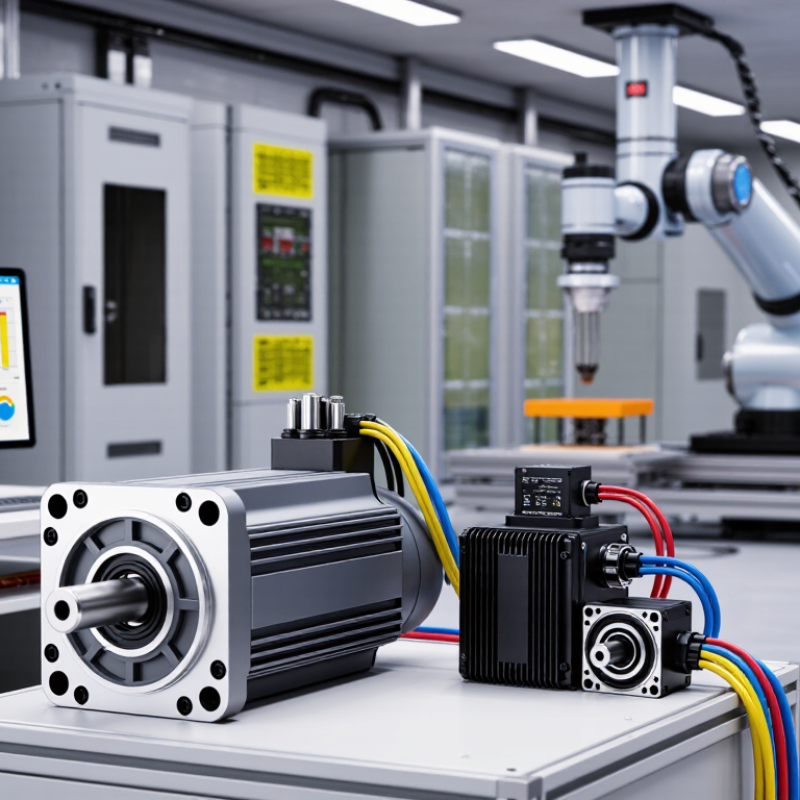
How to Choose a Servo Motor in 2026?
Servo motor selection should begin with the machine’s real motion profile, not the catalog’s largest torque value. Measure acceleration, deceleration, travel distance, and stopping time. Define continuous speed and peak speed separately. A motor running at 3,000 rpm may briefly reach 5,000 rpm. Check the drive and feedback system for that range.
Torque needs equal care. Calculate load torque, friction, gearbox losses, and acceleration torque. Use RMS torque to assess heating across the complete duty cycle. Peak torque must cover short overloads without causing unstable motion. Do not ignore reflected inertia. It can make a small load feel surprisingly heavy. Duty cycle descriptions should identify operating periods, pauses, reversals, and repeated peaks. S1 indicates continuous duty, while S3 describes intermittent periodic duty with starting and stopping intervals.
IEC 60034-1 ratings provide a consistent basis for motor output, voltage, frequency, speed, current, and thermal performance. Read the nameplate rating beside its duty designation. A motor rated for continuous operation may not deliver the same performance during frequent acceleration. Ambient temperature, installation position, cooling method, and enclosure protection also affect usable output. Calculate twice. Real machines are less tidy than spreadsheets. Leave practical margin, but avoid excessive oversizing because it can reduce responsiveness and increase system cost. A trial measurement often exposes assumptions that calculations miss.
| Selection Dimension | What to Define | Engineering Data or Formula | Practical Selection Guidance | Verification Point |
|---|---|---|---|---|
| 1. Application Requirements | ||||
| Load type | Rotary inertia, friction load, gravity load, or process load | Record the load inertia, transmission ratio, mechanical efficiency, and external resisting torque. | Gravity and vertical-axis applications normally require a brake, counterbalance, or continuous holding torque assessment. | Confirm the motor can control the load safely when power is removed. |
| Motion profile | Position, speed, acceleration, constant-speed, and deceleration segments | Define each segment by time, speed, acceleration, and load torque. | A complete motion profile is more reliable than selecting a motor from peak speed alone. | Use the worst-case profile, including start-up, stopping, reversing, and settling. |
| Transmission system | Gearbox, belt, screw, rack-and-pinion, coupling, or direct drive | For a reduction ratio i, the approximate reflected load inertia is: Jreflected = Jload / i2 | Higher reduction ratios can reduce reflected inertia and motor torque, but they also reduce output speed and may add backlash. | Include gearbox efficiency, backlash, compliance, and allowable radial or axial loads. |
| Environmental conditions | Ambient temperature, humidity, dust, washdown, altitude, vibration, and installation position | Motor and drive ratings must remain valid at the actual installation conditions. | Derating may be required at high altitude, high ambient temperature, restricted cooling, or frequent overload operation. | Check enclosure, insulation system, cooling method, mounting arrangement, and cable requirements. |
| 2. Speed Definition | ||||
| Required speed range | Minimum speed, nominal speed, maximum continuous speed, and maximum short-time speed | Specify speed in revolutions per minute (r/min or rpm). | Select a motor and drive whose permissible speed range covers the complete motion profile. | Verify speed limits at the actual bus voltage, load torque, temperature, and feedback resolution. |
| Acceleration speed | Peak speed during acceleration and deceleration | Angular acceleration: α = Δω / Δt | High acceleration requires sufficient peak torque and adequate drive current capacity. | Check whether the drive can supply peak current for the required acceleration time. |
| Speed-torque operating point | Continuous operating speed and torque | Mechanical power: P(kW) = T(N·m) × n(rpm) / 9550 | At a given power, torque decreases as speed increases. A motor must satisfy both speed and torque requirements. | Plot the complete operating points against the motor's continuous and intermittent speed-torque curves. |
| Constant-torque region | Speed range in which rated torque is available | Below the base speed, the motor commonly operates in a constant-torque region, subject to the drive and motor ratings. | Use this region for acceleration, low-speed positioning, and loads whose torque does not decrease with speed. | Confirm thermal limits at low speed because reduced cooling can limit continuous torque. |
| Constant-power region | Speed range above base speed | In a field-weakening or voltage-limited region, approximate power remains constant while available torque decreases: T ≈ 9550P / n | Do not assume rated torque is available at every speed above the base speed. | Use the manufacturer's generic motor curve for the selected frame and winding, without exceeding overspeed limits. |
| 3. Torque Definition | ||||
| Load torque | Torque required to overcome friction, process resistance, and gravity | Total required torque: Tload = Tfriction + Tprocess + Tgravity | Calculate torque at the motor shaft after considering transmission ratio and efficiency. | Use measured values where possible and include the worst credible process condition. |
| Acceleration torque | Torque needed to change motor and reflected load speed |
Taccel = Jtotal × α
where J is in kg·m² and α is in rad/s². |
Total motor torque is approximately: Tmotor = Tload + Taccel | Include motor rotor inertia, coupling inertia, gearbox inertia, and reflected load inertia. |
| Continuous torque | Torque required repeatedly or continuously without overheating | Compare the calculated thermal-equivalent torque with the motor's continuous rated torque. | A motor may meet peak torque but still be undersized thermally if its average or RMS torque is too high. | Check continuous torque at the actual speed and ambient temperature. |
| Peak torque | Short-duration torque during acceleration, deceleration, impact, or disturbance | Peak torque must remain within both the motor peak torque and the drive peak-current capability. | Use peak torque only for the specified duration and repetition rate; it is not a continuous rating. | Verify peak torque duration, thermal recovery time, and permissible overload cycles. |
| RMS torque | Thermal equivalent of a variable torque cycle | TRMS = √[(ΣTi2ti) / Σti] | Use RMS torque for repeated variable-load cycles, provided the motor thermal model and cooling conditions are appropriate. | RMS torque should normally be below the permissible continuous torque at the relevant speed. |
| Torque margin | Allowance for uncertainty, wear, friction variation, and process changes | A project-specific margin is applied to calculated continuous and peak torque. | Avoid excessive oversizing because it can increase cost, inertia, physical size, and tuning difficulty. | Document the margin separately from the calculated load requirement. |
| 4. Duty Cycle and Thermal Loading | ||||
| Cycle time | Time from the start of one motion sequence to the start of the next | tcycle = Σti | Include motion, dwell, braking, settling, loading, unloading, and idle periods. | Use the shortest realistic cycle because it creates the highest average thermal load. |
| Duty cycle percentage | Percentage of time the motor is actively operating | Duty cycle = operating time / total cycle time × 100% | For a 6-second move followed by a 4-second dwell, the operating duty cycle is 60%. | Do not treat a low duty percentage as automatically safe; high torque during the operating interval can still overheat the motor. |
| Intermittent periodic duty | Repeated operating and rest periods with a defined cycle | IEC 60034-1 identifies intermittent periodic duties in the S3 to S8 categories. | State load, speed, starting, braking, and rest conditions rather than reporting only a percentage. | Check the specified cycle duration and the number of starts or reversals per hour. |
| Motor heating | Temperature rise caused by current, speed, load, and cooling | Winding copper losses increase approximately with the square of current: Pcu ∝ I2 | Repeated high-current acceleration can create significant heating even when average mechanical power is modest. | Evaluate thermal performance using the motor-drive combination, installation position, and ambient temperature. |
| 5. IEC 60034-1 Duty Ratings | ||||
| S1 — Continuous running duty | Operation at a constant load long enough to reach thermal equilibrium | Continuous | Use when the motor runs continuously at a substantially constant load and speed. | Continuous rated power or torque must satisfy the actual steady-state operating point. |
| S2 — Short-time duty | Operation at constant load for a specified time, followed by a rest period sufficient to cool to ambient temperature | Common time descriptions include S2 10 min, S2 30 min, and S2 60 min. | Applicable when each operating period is isolated by a long cooling interval. | The operating duration must be stated; an S2 rating is not automatically suitable for repeated cycles. |
| S3 — Intermittent periodic duty | A sequence of identical operating and rest periods without significant starting or electrical braking influence | Typical duty-cycle values are expressed as percentages such as 15%, 25%, 40%, or 60%. | Use when the motor repeatedly runs under load and then rests. | Specify cycle duration and duty-cycle percentage; starting losses are generally excluded from the simplified S3 description. |
| S4 — Intermittent periodic duty with starting | Repeated cycles that include a significant starting period | Starting frequency and motor inertia influence thermal loading. | Use for frequent starts where acceleration current materially affects heating. | Verify starts per hour, acceleration time, load inertia, and starting current. |
| S5 — Intermittent periodic duty with electric braking | Repeated cycles that include starting, operation, electric braking, and rest | Braking energy and braking frequency are part of the duty assessment. | Use for repeated stop-start applications with dynamic or regenerative braking. | Check drive regeneration, braking resistor capacity, DC-bus voltage, and motor heating. |
| S6 — Continuous-operation periodic duty | Repeated cycles of load operation and no-load operation without rest | Thermal equilibrium is reached through alternating load and no-load periods. | Use when the motor continues rotating between loaded intervals rather than stopping. | Include no-load losses and confirm cooling at the lowest operating speed. |
| S7 — Continuous-operation periodic duty with electric braking | Repeated cycles of starting, operation, and electric braking without rest | There is no intended cooling rest period in the cycle. | Use for continuous stop-and-reverse or repeated electrically braked motion. | Evaluate thermal loading from acceleration, deceleration, and regenerative energy. |
| S8 — Continuous-operation periodic duty with related load and speed changes | Repeated cycles with specified combinations of load and speed | Each speed and load combination has a defined duration. | Use for machines that operate continuously but change speed and torque in a repeatable pattern. | Provide the complete load-speed-time sequence for accurate motor sizing. |
| S9 — Duty with non-periodic load and speed variations | Non-periodic changes in load and speed, including frequent overloads | Overloads, braking, and speed changes are irregular or unpredictable within specified limits. | Use for applications whose load profile cannot be represented by a simple repeating cycle. | Use a thermal simulation or conservative operating envelope and define permissible overloads. |
| S10 — Duty with discrete constant loads | A specified number of distinct load levels, each maintained for a sufficient duration | Each load level has a defined relative duration and thermal impact. | Use when the motor operates at several clearly defined steady load conditions. | State the load, speed, duration, and relative thermal lifetime contribution for each level. |
| 6. IEC 60034-1 Rating and Electrical Checks | ||||
| Rated power and torque | Declared mechanical output under specified operating conditions | For a rotating motor: Trated = 9550Prated(kW) / nrated(rpm) | Power alone is insufficient for servo selection; compare rated torque, peak torque, speed, and duty. | Confirm whether the published rating is continuous, short-time, or duty-specific. |
| Voltage and frequency | Supply voltage, frequency, phase configuration, and drive DC-bus voltage | IEC 60034-1 defines voltage and frequency variation zones for rotating electrical machines; the applicable supply conditions must be stated. | Servo motors are normally operated by a matched electronic drive, so motor-drive compatibility is essential. | Check current, insulation stress, cable length, grounding, EMC, and drive output limits. |
| Temperature rise and insulation | Winding temperature rise, insulation system, and permissible ambient temperature | Temperature limits depend on insulation class, temperature-rise method, ambient conditions, and the applicable rating. | Do not compare temperature-rise figures without checking the same test and rating conditions. | Verify winding protection, thermal sensor type, and drive fault response. |
| Protection and enclosure | Ingress protection, cooling method, and mechanical protection | IEC 60034-5 is commonly used for enclosure protection designations, while IEC 60034-6 addresses cooling methods. | Select protection for dust, water, washdown, oil mist, and the installation environment. | Confirm that the actual installation preserves the stated protection level. |
| Mounting and shaft loading | Mounting arrangement, shaft orientation, radial load, axial load, and coupling method | Permissible loads vary with speed, bearing arrangement, overhung distance, and service life. | Use a larger frame or external support if shaft loads exceed the motor's permissible values. | Check mounting code, bearing life, alignment, coupling balance, and shaft deflection. |
| 7. Final Servo Motor Selection Checklist | ||||
| Performance fit | Speed, continuous torque, peak torque, acceleration, and position accuracy | All required operating points must remain inside the permissible motor-drive envelope. | Choose the smallest motor that satisfies the complete profile with a documented engineering margin. | Review the speed-torque curve, peak-current curve, and feedback specifications. |
| Thermal fit | RMS torque, duty cycle, ambient temperature, cooling, and overload repetition | Use RMS calculations or a validated thermal model for variable-load operation. | Thermal sizing must account for low-speed cooling and repeated acceleration or braking. | Confirm continuous operation at the worst-case cycle, not only at the nominal cycle. |
| System compatibility | Drive, feedback, brake, cables, controller, safety circuit, and communications | The motor and drive must be compatible in voltage, current, feedback type, tuning, and control mode. | Specify the complete motor-drive system rather than treating the motor as an isolated component. | Check commissioning data, safety functions, cable shielding, braking energy, and fault handling. |
| Compliance documentation | Applicable standards, declared ratings, test conditions, and installation requirements | Record IEC 60034-1 duty designation, rated conditions, environmental limits, and test assumptions. | A clear rating statement prevents confusion between continuous, intermittent, and peak performance. | Retain the calculation sheet, motion profile, duty-cycle definition, and final motor-drive settings. |
Start with the machine’s real motion profile, not the largest catalog torque. Record acceleration, deceleration, travel distance, stopping time, and dwell periods. A spreadsheet helps, but real machines are messier.
Continuous speed describes normal operation. Peak speed covers brief movements, such as reaching 5,000 rpm from 3,000 rpm. Check whether the motor, drive, and feedback system support both ranges.
Include load torque, friction, acceleration torque, gearbox losses, and reflected inertia. Reflected inertia can make a small load feel unexpectedly heavy. Do not calculate from average load alone.
RMS torque estimates heating across the complete duty cycle. Peak torque covers short acceleration events, disturbances, and emergency stops. Both values matter.
A practical margin is usually 10–20 percent. Controlled laboratory motion may suit 10 percent. Rougher equipment may need 20 percent, but unexplained margin is only a guess.
Suppose the application needs 8 Nm RMS torque and 14 Nm peak torque. With a 20 percent margin, targets become 9.6 Nm RMS and 16.8 Nm peak. These values still require technical verification.
Describe operating periods, pauses, reversals, starting, stopping, and repeated peaks. S1 represents continuous duty, while S3 represents intermittent periodic duty. Timing details matter.
Read voltage, frequency, speed, current, thermal performance, and duty designation together. Confirm continuous torque at the actual operating speed. Ambient temperature, mounting position, cooling, and enclosure protection can reduce usable output.
Using average torque alone can hide repeated-start heating. I made that mistake once. Test the prototype at the hottest expected ambient condition, then recalculate after payload or cycle changes.
Choosing a Servo Motor in 2026 requires more than comparing headline power ratings. Begin by defining the application’s required speed, torque, duty cycle, and operating conditions, then confirm that the motor’s ratings align with IEC 60034-1. Calculate both RMS torque for continuous operation and peak torque for acceleration or sudden loads, adding a practical 10–20% engineering margin to improve reliability. Feedback resolution is equally important; a 17–23-bit encoder range can provide the accuracy and repeatability needed for demanding motion profiles.
The motor and drive should be evaluated as one system. Ensure the servo drive supports the required IEC 61800-5-2 functional safety features and matches the motor’s feedback interface and control needs. Finally, compare thermal performance, IP protection, energy efficiency, maintenance demands, and expected service life. A sound 2026 selection should focus on total lifecycle cost rather than purchase price alone, balancing precision, durability, safety, and long-term operating efficiency.

 Brea Tech Micro Motor